A '91 Stealth RC10 project

General discussion, builds/restorations, etc...

Moderators: scr8p, klavy69

Post Reply
User avatar
XLR8
Approved Member
Posts: 2924
Joined: Sun Feb 19, 2017 3:46 am
Location: north/central Alabama
Has thanked: 1132 times
Been thanked: 837 times

A '91 Stealth RC10 project

Post by XLR8 »

So I’ve just about wrapped up the design phase of this project with just one or two small details yet to sort out. Here's where the design stands at the moment...
91 Stealth 1.jpg
91 Stealth 2.jpg
91 Stealth 3.jpg
For the main chassis layout, I’ve depended heavily upon this photo that, I think, was provided to us by Curtis Husting.
'91 Stealth bottom view.JPG
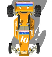
It's a great photo but of course it contains perspective, so I’ve struggled to find the correct length for the chassis plates (the wheelbase). It wasn’t until I fitted the body that I noticed, on Masami’s car, there is a relationship between the front body post (fitted atop the right bellcrank pivot post) and the two blisters located on either side of the body. You can see them here in a photo lifted from Steve Husting’s The Stealth RC10 Book.
Masami body post position.jpg
Masami body post position.jpg (69.34 KiB) Viewed 3878 times
Masami body post position.jpg
Masami body post position.jpg (69.34 KiB) Viewed 3878 times
As you probably already know, the blisters are meant to provide clearance for the heads of the screws that secure the nose support braces. As such, this should establish with reasonable accuracy the distance between the body post and the back face of the rear shock plate since this dimension likely wouldn’t have changed over time and through to the re-release of the RC10. With this revelation, I feel pretty confident that I'm on the right track.
91 Stealth 4.jpg
91 Stealth 4.jpg (56.31 KiB) Viewed 3878 times
91 Stealth 4.jpg
91 Stealth 4.jpg (56.31 KiB) Viewed 3878 times
The one remaining unknown, however, is the gap between the front edge of the bellcranks and the back face of the bulkhead. I’ve randomly set this to 0.047” because it will yield a nice round 11.25” total wheelbase… but I don’t know if this is accurate. Looking at some other photos of Masami’s car, this gap appears to be too small. So I need to ask a favor… If you’re fortunate enough to own one of these cars or a replica, would you be so kind as to pull it from the shelf, pop the body, and perform a quick visual inspection and let me know if a 0.047” gap is in the ballpark?
bulkhead to bellcrank gap.jpg
I should note here that the estimated 11.25” wheelbase is with suspension arms in neutral plane, zero front toe, rear suspension blocks with 1.5 degrees toe each side and standard rear hub carriers with zero degrees toe.
Anyway, if you’re able to help a brother out, I would be eternally grateful. :D
Doug

bluewormx
Approved Member
Posts: 343
Joined: Wed Jun 08, 2016 4:56 am
Location: Spain
Has thanked: 41 times
Been thanked: 90 times

Re: A '91 Stealth RC10 project

Post by bluewormx »

Great work so far. :D

If you look closely at the photos in the stealth book by Steve Hustings you will notice an "L" on the left rear hub carrier. (page 28)
That makes it a 1.5 deg as was standard on CE and Team car. Only short arm cars have zero deg rear hubs (no "L").

User avatar
XLR8
Approved Member
Posts: 2924
Joined: Sun Feb 19, 2017 3:46 am
Location: north/central Alabama
Has thanked: 1132 times
Been thanked: 837 times

Re: A '91 Stealth RC10 project

Post by XLR8 »

bluewormx wrote: Sat Aug 11, 2018 1:22 am Great work so far. :D

If you look closely at the photos in the stealth book by Steve Hustings you will notice an "L" on the left rear hub carrier. (page 28)
That makes it a 1.5 deg as was standard on CE and Team car. Only short arm cars have zero deg rear hubs (no "L").
That’s a very good point, thanks for mentioning it. I was aware that Masami’s car used the 1.5 degree carriers but I already had the standard ones modeled for another project, was rushed to make progress on this project so I threw them on as placeholders. I don’t think I have a set of the angled carriers to measure but I will speculate that if they were fitted onto this cad model and the wheelbase maintained at 11.25”, then the .047” gap in question would likely increase. Do you agree?
Doug

fredswain
Approved Member
Posts: 1167
Joined: Fri Mar 11, 2011 4:20 pm
Location: Houston
Been thanked: 4 times

Re: A '91 Stealth RC10 project

Post by fredswain »

Very cool to see someone else tackle this car in cad. Yours looks great. The wheelbase on my version when all arms are level is 11.125". Curtis gave us the exact length on the top deck so we know it's right. The rest of the wheelbase really comes down to interpretation of the arms. I still have a few tweaks on the overall shape of the front and rear towers. Now that there are at least 3 interpretations of the car, it would be interesting to see how close they all are to each other. The rear arm mounts on my version are 1.5° too btw. Great job!
Raborn Racing Originals Shapeways store

User avatar
XLR8
Approved Member
Posts: 2924
Joined: Sun Feb 19, 2017 3:46 am
Location: north/central Alabama
Has thanked: 1132 times
Been thanked: 837 times

Re: A '91 Stealth RC10 project

Post by XLR8 »

Thanks Fred. I know you’ve already gone through this process and have done a ton of research on this subject, so I really value your input here. I’m determined to see this project through to completion. To be honest, if this is my interpretation of this iconic car, it is limited only to the plate parts. I’m really just leveraging the work of others in order to fill a parts availability gap. The most challenging parts to recreate will be by others.

When I had returned to the hobby in 2014 and discovered this site, the most interesting thread I’d found to read was Jake’s (aka Seabass) and Niki’s posts journaling their experiences trying to recreate this car. What a fascinating read!! For anyone who’s new to this site and a fan of vintage racing buggies, I strongly recommend that you spend the time to read all 36 pages; I promise you won’t be disappointed. I won’t spoil it here, but I can say that the payoff toward the end is epic.
https://www.rc10talk.com/viewtopic.php?f=35&t=24084&hilit=91+Masami+Stealth+replica
Anyway, since that time, I have been determined to build a ’91 Stealth for myself.

Actually, as often happens when I set out to build an RC car, I’ve decided to build two cars; one runner and one replica. The runner will use Niki’s “racer” parts that were ordered from iMaterialize and printed in what they’ve described as a stronger material and an improved printing process (I guess we’ll see how strong they really are). I’ve decided to use aluminum for the runner’s main chassis partly because it’s something I can make in my shop but also because I’ll want to be able to experiment on-the-fly with alternative kick-up angles. We know from Curtis’ photo that the original car’s kick was 30 degree but seeing the break in Masami’s car's upper deck and photos of his car suggesting that perhaps his (static?) kick angle might have been something slightly different has piqued my curiosity regarding how a car’s handling can be affected by changing this angle. By the way, having a broken upper deck should have decreased his car’s torsional rigidity so his car certainly must have handled differently than any of the other team member’s cars. Anyway, the 6061 material I have for the chassis plate is malleable enough to allow for some minor angle changes and the forward screw holes in the top plate will be slotted as well to facilitate these changes.

As you’ve wisely pointed out elsewhere, a replica of Masami’s car will never drive exactly like his car for a number of reasons (the suspension part’s differing materials and manufacturing process being one of the principle reasons) but I’d like to get as many of the design details as right as possible and this includes wheelbase. I’ve determined the WB on the cad model by measuring between the front axle centerline and, at the rear, the intersection of the cross pin and axle centerline. With toe angle, where along the axle the measurement is taken matters. I guess the correct location would be at the center of the tire contact patch. Is this right?
Doug

fredswain
Approved Member
Posts: 1167
Joined: Fri Mar 11, 2011 4:20 pm
Location: Houston
Been thanked: 4 times

Re: A '91 Stealth RC10 project

Post by fredswain »

I've never modeled the shocks or a body so I haven't been able to compare a few things. I honestly don't think I'm good enough to model the body. I'm really more of a design and mechanical engineering based person and not an artistic or rendering based one. Years ago, Curtis had given us the wheelbases for the 89 and 91 cars but it was so long ago that it may be difficult to find that communication. The 89 car had a shorter wheelbase.
Raborn Racing Originals Shapeways store

User avatar
XLR8
Approved Member
Posts: 2924
Joined: Sun Feb 19, 2017 3:46 am
Location: north/central Alabama
Has thanked: 1132 times
Been thanked: 837 times

Re: A '91 Stealth RC10 project

Post by XLR8 »

I'm with ya Fred, I have absolutely no artistic talent whatsoever. To digitize complex shapes like a body, I'll need a couple reference photos that don't include perspective to trace. So, to make said photos, I first attach the body to a small wooden sled set on a table
that I can guided accurately against a 48" aluminum ruler that's fixed to the table. I'll set up a camera on a tripod and position it such that is as close as possible to 90 degrees from the side of the body (or from the top if that's what I'm attempting to digitize). I begin at the front of the body and snap a pic every 2", advancing the sled and body each time (the camera must remain stationary). When I've finished, I can take the 7 or 8 pics and edit them into a single composite photo that has nearly all perspective removed. I do this for the side and the top view and then it's a simple matter of importing these images into cad, trace the outlines, and extrude these shapes into 3d space. There's usually a lot of tweaking and cleanup work to do because the reference images don't always lineup perfectly and the models edges require radius, etc. I will take careful measurements of key features on the body and adjust the cad model accordingly. When the cad model is finished, I will print a side and top view and lay the body over the printout to make sure everything lines up correctly. It's kinda fussy but it works. Here's one of the composite images I used to digitize a Viper body.
side composite.jpg
I pulled one of the rear hub carriers from my CE (1.5 degree toe) and I've also found in a box of wheels a set of the Yok wheels Masami used so I can model them. With these two parts fitted to the cad model, I can dial-in the wheelbase and wrap-up the chassis design.

I think it makes sense that the 89 car would be shorter wheelbase since it used the same chassis as the 91 but the front suspension on the 89 car is the right way around so the front axles are farther aft like a typical production RC10.
Doug

fredswain
Approved Member
Posts: 1167
Joined: Fri Mar 11, 2011 4:20 pm
Location: Houston
Been thanked: 4 times

Re: A '91 Stealth RC10 project

Post by fredswain »

The 89 chassis is actually longer.
Raborn Racing Originals Shapeways store

User avatar
XLR8
Approved Member
Posts: 2924
Joined: Sun Feb 19, 2017 3:46 am
Location: north/central Alabama
Has thanked: 1132 times
Been thanked: 837 times

Re: A '91 Stealth RC10 project

Post by XLR8 »

fredswain wrote: Tue Aug 14, 2018 9:30 pm The 89 chassis is actually longer.
You’re right Fred.
I’d recalled reading somewhere on this forum, someone mentioned that the differences between the ‘89 and ‘91 cars were mostly limited to the front suspension, so I’d just assumed that meant that the main chassis was the same for both cars. … and they certainly appear to be the same.
So, I’ve found a bottom view photo of the ‘89 car and compared it to a similar photo of the ‘91 car (I’m guessing that both photos are by Curtis). After adjusting the image scale so that the chassis are the same width and aligning their rear bulkhead screws, it's easy to see that the ‘89’s chassis is longer.
I’ve also noticed another thing; the 89's transmission screw pattern doesn’t appear to match a production Stealth transmission (the spacing for rear screw holes are too wide). Did the ‘89 car use an early Stealth prototype perhaps?? So, a quick check of the images in The Stealth RC10 Book and, sure enough, the ‘89 car used a different transmission. Holy cow, I guess when you’re AE and have vast resources at your disposal, you can do just about anything including building and racing a one-off prototype. I tend to think of AE as RC’s version of an F1 constructor.
89 vs 91.jpg
Doug

User avatar
scr8p
Administrator
Posts: 16521
Joined: Tue Feb 07, 2006 9:46 pm
Location: Northampton, PA
Has thanked: 28 times
Been thanked: 955 times

Re: A '91 Stealth RC10 project

Post by scr8p »

14957837639_8525a7ff9d_b.jpg
14957979327_b683b6c8f4_b.jpg

bluewormx
Approved Member
Posts: 343
Joined: Wed Jun 08, 2016 4:56 am
Location: Spain
Has thanked: 41 times
Been thanked: 90 times

Re: A '91 Stealth RC10 project

Post by bluewormx »

scr8p wrote: Wed Aug 15, 2018 5:12 pm 14957837639_8525a7ff9d_b.jpg
14957979327_b683b6c8f4_b.jpg
Ninja!

As the story goes there where only three stealth cars made for the 89 worlds in Australia: Masami, Cliff Lett and Jay Halsey had these cars. Some of the other team drivers had regular RC10 but with prototype stealth transmissions. Craig Dresher had one and he made the A main, not sure who else had one.

Great find Jason. :D

User avatar
XLR8
Approved Member
Posts: 2924
Joined: Sun Feb 19, 2017 3:46 am
Location: north/central Alabama
Has thanked: 1132 times
Been thanked: 837 times

Re: A '91 Stealth RC10 project

Post by XLR8 »

Cool! Do we know if it was 2.25:1? The slipper looks like the production version.
I'd never thought about this before but it's looking like the '89 car actually used more prototype parts than the '91. Interesting! When someone mentions Masami's Stealth RC10, for some reason I'd always imagined the '91 and considered it the more radical design. Little do I know.
Doug

User avatar
scr8p
Administrator
Posts: 16521
Joined: Tue Feb 07, 2006 9:46 pm
Location: Northampton, PA
Has thanked: 28 times
Been thanked: 955 times

Re: A '91 Stealth RC10 project

Post by scr8p »

Mark Pavidis posted those trans pics on FB a few years ago. I guess he was going through a box of old stuff and came across it.

The '91 car still has more prototype parts on it than the '89 car. If you break it down:

Same parts - f & r arms, front bulkheads, front shock towers, rear arm mounts

Now where they differ:

'91 - castor blocks, steering knuckles, steering bellcrank, rear shock tower

'89 - trans case

User avatar
XLR8
Approved Member
Posts: 2924
Joined: Sun Feb 19, 2017 3:46 am
Location: north/central Alabama
Has thanked: 1132 times
Been thanked: 837 times

Re: A '91 Stealth RC10 project

Post by XLR8 »

Thanks scr8p. I’ll confess that I may be using the term “prototype” incorrectly as I've tended to equate it to any non-production (or pre-production) part irrespective of how it was made. So to me, a molded part could be a prototype if parts that were made from the same mold never found their way into a kit offered for sale to the public. My experience with the Rc10 ended when I left the hobby in early ‘90’s and long before the release of Worlds car so it’s possible that I’m misidentifying parts as “non-production” simply because I don’t recognize them.
BTW, I don’t recognize this axle; do you know if it's a production part? It has a flange that appears to be about 5/16” diameter. I probably could make them but it takes time, so I’d rather buy them if they are still available (and if they don’t cost a fortune).
Attachments
STEERING2.jpg
STEERING2.jpg (44.89 KiB) Viewed 3647 times
STEERING2.jpg
STEERING2.jpg (44.89 KiB) Viewed 3647 times
Doug

fredswain
Approved Member
Posts: 1167
Joined: Fri Mar 11, 2011 4:20 pm
Location: Houston
Been thanked: 4 times

Re: A '91 Stealth RC10 project

Post by fredswain »

I've got several pictures of the 89 car. Here's an early version that they used to develop the 91 front end. They merely reversed the 89 arms at first and started reworking from there.
Attachments
5%20caster%20and%20steering%20blocks%20assembled.jpg
5%20caster%20and%20steering%20blocks%20assembled.jpg (38.43 KiB) Viewed 3643 times
5%20caster%20and%20steering%20blocks%20assembled.jpg
5%20caster%20and%20steering%20blocks%20assembled.jpg (38.43 KiB) Viewed 3643 times
Raborn Racing Originals Shapeways store

Post Reply

Create an account or sign in to join the discussion

You need to be a member in order to post a reply

Create an account

Not a member? register to join our community
Members can start their own topics & subscribe to topics
It’s free and only takes a minute

Register

Sign in

  • Similar Topics
    Replies
    Views
    Last post
  • Project "RC10 Stealth-4" by mini (July 28th, 2015 updated)
    by minimini » » in RC10 Buggy Forum
    74 Replies
    9927 Views
    Last post by minimini
  • RC10 Graphite "Stealth" project
    by works92 » » in RC10 Buggy Forum
    19 Replies
    4389 Views
    Last post by mk-Zero
  • rc10 "stealth" project-completish
    by Winger » » in RC10 Buggy Forum
    35 Replies
    3953 Views
    Last post by Winger
  • stealth graphite project
    by rctenracer » » in RC10 Buggy Forum
    4 Replies
    794 Views
    Last post by rctenracer
  • Project stealth graphite is done!!!!
    by Roadrashracing » » in RC10 Buggy Forum
    16 Replies
    1837 Views
    Last post by Mr Casual
  • Project StealthMode...Minus The STEALTH
    by LTO_Dave » » in RC10 Buggy Forum
    28 Replies
    3336 Views
    Last post by n20capri
  • Paint: Hot Bodies Stealth Fighter Project
    by mikedealer » » in RC10 Buggy Forum
    7 Replies
    577 Views
    Last post by markt311
  • [Project] Restore My Black Stealth RC10CE Destroyed by Sandy
    by MeltingPlastic » » in RC10 Buggy Forum
    21 Replies
    3630 Views
    Last post by MeltingPlastic

Return to “RC10 Buggy Forum”

Who is online

Users browsing this forum: No User AvatarFacebook [Bot] and 1 guest