A '91 Stealth RC10 project
-
XLR8
- Approved Member
- Posts: 3307
- Joined: Sun Feb 19, 2017 3:46 am
- Location: north/central Alabama
- Has thanked: 1659 times
- Been thanked: 1170 times
-
XLR8
- Approved Member
- Posts: 3307
- Joined: Sun Feb 19, 2017 3:46 am
- Location: north/central Alabama
- Has thanked: 1659 times
- Been thanked: 1170 times
Re: A '91 Stealth RC10 project
Okay, shock towers, battery strap and motor guard are finished.
The NIX 91 “Racer” set from i.materialise includes a nicely designed 3d printed motor guard but I chose to make one from aluminum instead to take advantage of the material’s high thermal conductivity properties. Having the aluminum motor plate, motor guard and chassis all tightly screwed together should form a nice big heat sink and help to cool the motor.
Next up; bumper and rear bulkhead mods and further trial assembly of printed parts. Stay tuned.
Doug
-
GoMachV

- Approved Member
- Posts: 12214
- Joined: Sun Apr 29, 2012 10:31 pm
- Location: Twin Falls, ID
- Has thanked: 1084 times
- Been thanked: 3762 times
Re: A '91 Stealth RC10 project
Just a FYI- the RPM black motor guards are still available- same as the gold associated ones. You have to call to order them but they are cheap
-
XLR8
- Approved Member
- Posts: 3307
- Joined: Sun Feb 19, 2017 3:46 am
- Location: north/central Alabama
- Has thanked: 1659 times
- Been thanked: 1170 times
Re: A '91 Stealth RC10 project
Thanks. I'd like to have a gold one for my Graphite car. Are you saying that RPM has the gold ones but I'll need to call to order them (I don't see them listed on AE's website)?
Doug
-
GoMachV
- Approved Member
- Posts: 12214
- Joined: Sun Apr 29, 2012 10:31 pm
- Location: Twin Falls, ID
- Has thanked: 1084 times
- Been thanked: 3762 times
Re: A '91 Stealth RC10 project
Correct, rpm sells black only. They are leftovers from the ultra molded kits. They are the same as the gold ones, associated sold them to rpm way back in the day
-
XLR8
- Approved Member
- Posts: 3307
- Joined: Sun Feb 19, 2017 3:46 am
- Location: north/central Alabama
- Has thanked: 1659 times
- Been thanked: 1170 times
Re: A '91 Stealth RC10 project
Assembly continues but it’s time for an update.
Arms, links, and shocks are fitted. I’ve turned some aluminum spacers for the top and bottom of each shock. The top spacers are threaded and effectively replace the nut that’s normally used to secure the screw to the shock tower. The bottom spacers are just simple collars.
The rear bulkhead has been modified and I’ve decided to retain the wing tubes for this car (more about that later).
The bumper is also finished. Kydex is very easy to work with; it cuts like butter and bends easily (with help from a heat gun) and, once it’s cooled, holds the shape like it was molded that way.
Most of the components are fitting well however I’ve discovered interference between the chassis and the rear suspension arm and this is preventing full droop. When I made the CAD model, all suspension arms were placed at the neutral plane (ride height) so apparently, I didn’t provide enough clearance under the pivot to allow the arm to drop. I’ll fix the problem by removing some material from the chassis plate when I pull the car apart for painting and finishing.
Masami’s car had a similar problem, but they chose to mod the arm and not the chassis plate.
I’m using set screws rather than the typical e-clips to retain the hinge pins. This solves a couple of problems; no fumbling with e-clips (I really hate installing them – who doesn’t?) and the screws effectively remove some of the looseness in the hinge pins from those oversized pin holes in some of the 3d printed parts. In fact, with the set screws fully tightened, there’s only a small amount of looseness remaining at the hinge, so I really don’t feel the need to fit oversized pins (that 3.5mm rod stock that I’d bought earlier). If the hinges loosen over time I can replace the current 1/8” pins with the 3.5mm rods.
I will use an e-clip for the castor blocks however; that part’s vertical pin is retained with a clip on the bottom plus the normal set screw through the center of the axle. The clip is necessary to distribute some of the suspension loading to the lower pivot on that part. Without the bottom clip, the car’s weight and all bump forces from the wheel would transfer to the block’s upper pivot alone and this could lead to a part failure.
When I pull the car apart, I’ll turn a shallow recess in each pin at the set screw contact point. The screw can key into this recess, locking the pin and prevent it falling out if the screw should loosen.
I’ve found the paint I’ll use for the printed parts. It’s not a perfect match to the nylon but it’s close. I’ll try wet-sanding the parts before painting them to remove some of the rough surface texture and, perhaps, reduce some of the stress risers that might lead to a fracture.
Next are bell-cranks and steering. Stay tuned. 
Arms, links, and shocks are fitted. I’ve turned some aluminum spacers for the top and bottom of each shock. The top spacers are threaded and effectively replace the nut that’s normally used to secure the screw to the shock tower. The bottom spacers are just simple collars.
- interference masami.JPG (58.64 KiB) Viewed 3172 times
- interference masami.JPG (58.64 KiB) Viewed 3172 times
I will use an e-clip for the castor blocks however; that part’s vertical pin is retained with a clip on the bottom plus the normal set screw through the center of the axle. The clip is necessary to distribute some of the suspension loading to the lower pivot on that part. Without the bottom clip, the car’s weight and all bump forces from the wheel would transfer to the block’s upper pivot alone and this could lead to a part failure.
When I pull the car apart, I’ll turn a shallow recess in each pin at the set screw contact point. The screw can key into this recess, locking the pin and prevent it falling out if the screw should loosen.
Doug
-
NomadRacer

- Approved Member
- Posts: 1467
- Joined: Sun Apr 16, 2017 7:29 am
- Location: Eastern Shore of Virginia
- Has thanked: 81 times
- Been thanked: 79 times
Re: A '91 Stealth RC10 project
It's looking really nice. Love the bumper, excellent shape on that part! It looks like you could counter sink the screws?
Bum on Direct Deposit
-
XLR8
- Approved Member
- Posts: 3307
- Joined: Sun Feb 19, 2017 3:46 am
- Location: north/central Alabama
- Has thanked: 1659 times
- Been thanked: 1170 times
Re: A '91 Stealth RC10 project
Thank you Mr. Nomad sir.
Yeah, I'm sorta proud of that bumper.
Actually, I did countersink the bumper screw holes but just not far enough. Also, I haven't ran the screws in very tight.
Yeah, I'm sorta proud of that bumper.
Actually, I did countersink the bumper screw holes but just not far enough. Also, I haven't ran the screws in very tight.
Doug
-
NomadRacer
- Approved Member
- Posts: 1467
- Joined: Sun Apr 16, 2017 7:29 am
- Location: Eastern Shore of Virginia
- Has thanked: 81 times
- Been thanked: 79 times
Re: A '91 Stealth RC10 project
I hear ya man. Counter sinking for screws flat heads screws is soooo tricky! I use a screw that has the threads filed off. It will drop in the hole nicely for checking the depth of the counter sink. I don't have a stop on my drill press!
Bum on Direct Deposit
-
XLR8
- Approved Member
- Posts: 3307
- Joined: Sun Feb 19, 2017 3:46 am
- Location: north/central Alabama
- Has thanked: 1659 times
- Been thanked: 1170 times
Re: A '91 Stealth RC10 project
Hi Mike. Yes, probably tomorrow or Monday. There's lots of little steering system details and they're taking some time to sort out.
The trial assembly phase is almost done so this next build update will likely be the last one before the car is disassembled for painting and finishing.
Stay tuned.
The trial assembly phase is almost done so this next build update will likely be the last one before the car is disassembled for painting and finishing.
Stay tuned.
Doug
-
XLR8
- Approved Member
- Posts: 3307
- Joined: Sun Feb 19, 2017 3:46 am
- Location: north/central Alabama
- Has thanked: 1659 times
- Been thanked: 1170 times
Re: A '91 Stealth RC10 project
Okay, as promised, here’s an update…
Beginning with bell cranks. I’ve gone ahead and turned a set of bell crank posts (with front body mount) from aluminum. I could use the posts that came with the NIX 91 racer set but these will be a bit more durable and less prone to flex. The body pin hole will be located and drilled after the body has been fitted.
The servo is screwed to the chassis plate using AE 6337 mounting blocks and the steering system is completed.
Both front arms will require a notch to allow the bell cranks to rotate fully at maximum suspension compression.
Here’s the notch from the bottom side. I guess it could have been included as a feature of the arm’s design however this would have resulted in specific left and right arms. As they are received from the printer, the arms are symmetrical and can be installed on either side before cutting-in this notch.
I really don’t consider this a mistake since Masami’s car also included a similar modification.
Anyway, here’s the completed assembly. For the next build update, the printed parts will be painted, electrics installed and, maybe, the body will be mounted.
Beginning with bell cranks. I’ve gone ahead and turned a set of bell crank posts (with front body mount) from aluminum. I could use the posts that came with the NIX 91 racer set but these will be a bit more durable and less prone to flex. The body pin hole will be located and drilled after the body has been fitted.
- masami arm notch.jpg (70.24 KiB) Viewed 3063 times
- masami arm notch.jpg (70.24 KiB) Viewed 3063 times
Doug
-
XLR8
- Approved Member
- Posts: 3307
- Joined: Sun Feb 19, 2017 3:46 am
- Location: north/central Alabama
- Has thanked: 1659 times
- Been thanked: 1170 times
Re: A '91 Stealth RC10 project
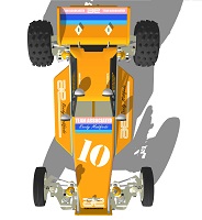
A couple more pics that I couldn't attach to the previous post for some reason.
Doug
Create an account or sign in to join the discussion
You need to be a member in order to post a reply
Create an account
Not a member? register to join our community
Members can start their own topics & subscribe to topics
It’s free and only takes a minute
Sign in
-
- Similar Topics
- Replies
- Views
- Last post
-
- 74 Replies
- 11120 Views
-
Last post by minimini
-
- 35 Replies
- 4477 Views
-
Last post by Winger
-
- 19 Replies
- 4757 Views
-
Last post by mk-Zero
-
- 16 Replies
- 2308 Views
-
Last post by Mr Casual
-
- 4 Replies
- 975 Views
-
Last post by rctenracer
-
- 28 Replies
- 3705 Views
-
Last post by n20capri
-
- 7 Replies
- 769 Views
-
Last post by markt311
-
- 21 Replies
- 4021 Views
-
Last post by MeltingPlastic
Who is online
Users browsing this forum: ![]() Ahrefs [Bot] and 5 guests
Ahrefs [Bot] and 5 guests