This set of pics all look fairly similar to each other but there are incremental changes from the last post.
Legit ball stud spacers (9630) instead of placeholder washers.
9577 inline steering blocks installed. 1" wide wheels clearance is good and 3/4" wide wheels is plenty.
New 8442b axels.
Tweeked the shims, spacers and honed the hinge pin holes where needed.
With the 9577 steering blocks, the angle and length (as well as being stronger), very closely simulates the B6.2 box stock setup.
However this does not allow for the numerous tuning nuances a b6.2 would have.
After setting toe and camber to spec I went back and checked AE manual for the spacing between the ball cups on the turnbuckles and the measurements were spot on.
Overall width with tires on is right at 250mm at 20mm ride height. Front axel to rear axel is at 11 1/2" at 20mm ride height. I could move the rear arms forward 2-3 mm by changing spacer location if needed.
More to come
Chuck
Mid-motor B1, B4, B6 V2
-
radioactivity

- Approved Member
- Posts: 858
- Joined: Wed Jan 24, 2018 11:46 am
- Location: Dripping Springs Tx
- Has thanked: 384 times
- Been thanked: 618 times
Re: Mid-motor B1, B4, B6 V2
- Attachments
-
-
-
-
Hydrodip how to https://www.rc10talk.com/viewtopic.php?f=62&t=42727
When all you have is a hammer everything looks like a nail
When all you have is a hammer everything looks like a nail
-
radioactivity
- Approved Member
- Posts: 858
- Joined: Wed Jan 24, 2018 11:46 am
- Location: Dripping Springs Tx
- Has thanked: 384 times
- Been thanked: 618 times
Re: Mid-motor B1, B4, B6 V2
A problem I found in mounting a "standard" servo was the servo horn hitting the underside of top plate.
This was because the nose piece on a vintage RC10 steps up and overlaps the floor of the chassis by about 2.5mm. This raises the servo and caused the interference between the horn and top plate. I tried every servo horn I had with a standard size servo, to no avail. I also wanted to use the B6.2 servo horn to stay fairly true to the B6.2 steering geometry.
Very tight tolerances in the original B6.2 design, but they may not have anticipated me doing this build.
So I’ve been on what seems to be an “Epic Quest” for a reasonable cost mini servo.
Some parameters were.
1. A $50.00 budget.
2. No more than 15mm in width. Or actually in height when mounted in a car.
3. A decent amount of torque of at least 70-80 oz/in.
4. Pretty much any reasonable speed, too old for super lightning fast servos.
5. Metal gears, ball bearings
6. Conventional spline count of 23t, 24t or 25t. No mini splines.
I thought a Spektrum A5060 might do the trick but when it arrived…
Unconventional spline (still don’t know what it was)
The output shaft was not tapped for the retaining screw.
So back it went to the supplier, and got a credit for the purchase.
So I threw out parameter #1 and almost doubled the cost of the servo to get…
SV1261MG - Mini Digital High Voltage Aluminum Case Servo
1. An $85 budget.
2. Exactly 15mm width
3. Torque @6v 207 oz/in
4. Speed @6v 0.12 sec/60 deg
5. Metal gears, ball bearings
6. Conventional spline with 25t count.
Need to make some custom mounts for the servo but plenty of clearance, not only a lower output spline but more centered.
Maybe replace the servo horn I butchered trying to get the standard servo to fit.
Chuck
This was because the nose piece on a vintage RC10 steps up and overlaps the floor of the chassis by about 2.5mm. This raises the servo and caused the interference between the horn and top plate. I tried every servo horn I had with a standard size servo, to no avail. I also wanted to use the B6.2 servo horn to stay fairly true to the B6.2 steering geometry.
Very tight tolerances in the original B6.2 design, but they may not have anticipated me doing this build.
- interfere.JPG (38.8 KiB) Viewed 2654 times
- interfere.JPG (38.8 KiB) Viewed 2654 times
Some parameters were.
1. A $50.00 budget.
2. No more than 15mm in width. Or actually in height when mounted in a car.
3. A decent amount of torque of at least 70-80 oz/in.
4. Pretty much any reasonable speed, too old for super lightning fast servos.
5. Metal gears, ball bearings
6. Conventional spline count of 23t, 24t or 25t. No mini splines.
I thought a Spektrum A5060 might do the trick but when it arrived…
Unconventional spline (still don’t know what it was)
The output shaft was not tapped for the retaining screw.
So back it went to the supplier, and got a credit for the purchase.
So I threw out parameter #1 and almost doubled the cost of the servo to get…
SV1261MG - Mini Digital High Voltage Aluminum Case Servo
2. Exactly 15mm width
3. Torque @6v 207 oz/in
4. Speed @6v 0.12 sec/60 deg
5. Metal gears, ball bearings
6. Conventional spline with 25t count.
Need to make some custom mounts for the servo but plenty of clearance, not only a lower output spline but more centered.
Maybe replace the servo horn I butchered trying to get the standard servo to fit.
Chuck
Hydrodip how to https://www.rc10talk.com/viewtopic.php?f=62&t=42727
When all you have is a hammer everything looks like a nail
When all you have is a hammer everything looks like a nail
-
XLR8
- Approved Member
- Posts: 3319
- Joined: Sun Feb 19, 2017 3:46 am
- Location: north/central Alabama
- Has thanked: 1686 times
- Been thanked: 1181 times
Re: Mid-motor B1, B4, B6 V2
When it comes to electronics, especially a servo, I usually run the most economical one can find.
I understand that a Savox was a bit of a budget buster but a build this nice deserves a premium servo. ... and it certainly looks great in this car.
I understand that a Savox was a bit of a budget buster but a build this nice deserves a premium servo. ... and it certainly looks great in this car.
Doug
-
radioactivity
- Approved Member
- Posts: 858
- Joined: Wed Jan 24, 2018 11:46 am
- Location: Dripping Springs Tx
- Has thanked: 384 times
- Been thanked: 618 times
Re: Mid-motor B1, B4, B6 V2
This is where I gained plenty of servo horn clearance.
The Savox servo output shaft is more centered and is also 2.5mm lower toward the chassis.
That places the shaft at the same height as it is on a B6.2.
It doesn't seem like much but clearances under and around the B6.2 top plate are quite close.
The Reedy servo is a "standard" size servo, the Savox is a "mini" servo.
Chuck
- Attachments
-
Hydrodip how to https://www.rc10talk.com/viewtopic.php?f=62&t=42727
When all you have is a hammer everything looks like a nail
When all you have is a hammer everything looks like a nail
-
radioactivity
- Approved Member
- Posts: 858
- Joined: Wed Jan 24, 2018 11:46 am
- Location: Dripping Springs Tx
- Has thanked: 384 times
- Been thanked: 618 times
Re: Mid-motor B1, B4, B6 V2
It would be nice to find a pair of curved bellcrank arms that have a ballstud mount on the right arm instead of the left arm.
Then I would flip the servo over and the lettering on the case would be right side up. Slight case of OCD.
Anyone know if B6 arms would fit?
These will allow ballstud on either side but it's so close.
Chuck
Then I would flip the servo over and the lettering on the case would be right side up. Slight case of OCD.
Anyone know if B6 arms would fit?
- bcrank.JPG (25.56 KiB) Viewed 2547 times
- bcrank.JPG (25.56 KiB) Viewed 2547 times
Chuck
Hydrodip how to https://www.rc10talk.com/viewtopic.php?f=62&t=42727
When all you have is a hammer everything looks like a nail
When all you have is a hammer everything looks like a nail
-
radioactivity
- Approved Member
- Posts: 858
- Joined: Wed Jan 24, 2018 11:46 am
- Location: Dripping Springs Tx
- Has thanked: 384 times
- Been thanked: 618 times
Re: Mid-motor B1, B4, B6 V2
So don't go looking for a "mini" sized servo mount. At least any place I looked.
Found some 6061 aluminum bar in 1/2" X 1/2" X 12" and cut a few pieces off the end.
My miter saw with a Diablo 80 tooth carbide tipped blade cut clean with no problems.
Sand paper from 220-2500 grit then Dremel and finally a rag and silver polish.
Drilled and tapped for 4-40.
The mounts wound up being .72" in height.
Fit in the chassis is almost perfect
I may clear anodize them to keep them from getting too scratched or oxidized.
Chuck
- Attachments
-
Hydrodip how to https://www.rc10talk.com/viewtopic.php?f=62&t=42727
When all you have is a hammer everything looks like a nail
When all you have is a hammer everything looks like a nail
-
radioactivity
- Approved Member
- Posts: 858
- Joined: Wed Jan 24, 2018 11:46 am
- Location: Dripping Springs Tx
- Has thanked: 384 times
- Been thanked: 618 times
Re: Mid-motor B1, B4, B6 V2
Got a couple new pieces and servo horn clearance is no longer a problem.
1. A new Associated 91654 top plate because I'd tried to clearance the underside of first top plate when it came into contact with the servo horn using a standard servo.
Thought it weakened the top plate when I cut it.
2. A new Associated 1366 servo horn, because again I had cut the plastic horn a bit.
3. And and pair of Associated 91668 bellcranks that allowed a right side ballstud placement and turning the Savox servo the right side up.
Also clear anodized the aluminum servo mounts. The servo is in there pretty solid now.
Chuck
Hydrodip how to https://www.rc10talk.com/viewtopic.php?f=62&t=42727
When all you have is a hammer everything looks like a nail
When all you have is a hammer everything looks like a nail
-
radioactivity
- Approved Member
- Posts: 858
- Joined: Wed Jan 24, 2018 11:46 am
- Location: Dripping Springs Tx
- Has thanked: 384 times
- Been thanked: 618 times
Re: Mid-motor B1, B4, B6 V2
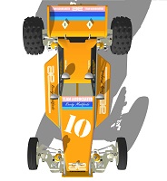
Been looking for a body long enough...
Got this one from Sabula tech.
Really wasn't sure if it would fit but it just barely does.
Wing is a Raw Speed B6.1/B6.2 style.
Waiting on decals
Chuck
Got this one from Sabula tech.
Really wasn't sure if it would fit but it just barely does.
Wing is a Raw Speed B6.1/B6.2 style.
Chuck
Hydrodip how to https://www.rc10talk.com/viewtopic.php?f=62&t=42727
When all you have is a hammer everything looks like a nail
When all you have is a hammer everything looks like a nail
-
XLR8
- Approved Member
- Posts: 3319
- Joined: Sun Feb 19, 2017 3:46 am
- Location: north/central Alabama
- Has thanked: 1686 times
- Been thanked: 1181 times
Re: Mid-motor B1, B4, B6 V2
Looks great Chuck.
The body fits surprisingly well and perhaps it's due in part to the fact that you've retained the rear shocks in their original location.
A lot of RC10 mid conversions that I've seen move the shocks and tower behind the axle and I think this can make it difficult find a body that fits well.
Anyway, this build is a really nice blend of old and new RC10.
Doug
-
radioactivity
- Approved Member
- Posts: 858
- Joined: Wed Jan 24, 2018 11:46 am
- Location: Dripping Springs Tx
- Has thanked: 384 times
- Been thanked: 618 times
Re: Mid-motor B1, B4, B6 V2
Thanks Doug
"A lot of RC10 mid conversions that I've seen move the shocks and tower behind the axle and I think this can make it difficult find a body that fits well."
Well... sort of
The original 6 gear transmission mounting holes kind of dictate where additional B6.2 trans mount holes can be placed, at least in my mind. Keeping the swiss cheese effect to a minimum.
In turn the trans position dictates where the arms and shock attachment on the arms are located.
So on this car, unlike Version 1, I did not space the shock tower forward.
Any how there is about a 12mm difference in the B6.2 tower and a stock tower.
What I do like is how the shocks tuck neatly into the body.
Camera position in pic above makes it pretty much impossible to see. So the better angle and close-up.
Chuck
"A lot of RC10 mid conversions that I've seen move the shocks and tower behind the axle and I think this can make it difficult find a body that fits well."
Well... sort of
The original 6 gear transmission mounting holes kind of dictate where additional B6.2 trans mount holes can be placed, at least in my mind. Keeping the swiss cheese effect to a minimum.
In turn the trans position dictates where the arms and shock attachment on the arms are located.
So on this car, unlike Version 1, I did not space the shock tower forward.
Any how there is about a 12mm difference in the B6.2 tower and a stock tower.
What I do like is how the shocks tuck neatly into the body.
Camera position in pic above makes it pretty much impossible to see. So the better angle and close-up.
Hydrodip how to https://www.rc10talk.com/viewtopic.php?f=62&t=42727
When all you have is a hammer everything looks like a nail
When all you have is a hammer everything looks like a nail
-
juicedcoupe

- Super Member
- Posts: 3567
- Joined: Sun Aug 16, 2020 4:05 pm
- Location: Pascagoula, MS
- Has thanked: 273 times
- Been thanked: 2108 times
Re: Mid-motor B1, B4, B6 V2
I know its a little late bot Losi TLR 231083 mounts are a good match for some mini servos.
All four holes line up on a Futaba S132H but only two line up on the smaller Hobbico (Hitec).
All four holes line up on a Futaba S132H but only two line up on the smaller Hobbico (Hitec).
- Attachments
-
-
Always looking for new and interesting ways to waste money.
-
adam lancia
- Approved Member
- Posts: 1116
- Joined: Tue Feb 05, 2008 6:37 pm
- Location: Donkin, Nova Scotia, Canada
- Has thanked: 7 times
- Been thanked: 42 times
Re: Mid-motor B1, B4, B6 V2
This is such a cool build  Thanks for sharing it.
I was thinking about your front brace issue (which looks solved) but would you have been able to modify the aluminum chassis to accept B6 chassis rails...? Those would have mated up to the front brace and given you some added rigidity in that area. I'm thinking of doing something similar, but with a flat sheet of 4mm carbon fiber, Ultima Pro XL rear end, A&L Lethal Weapon, and a B4 front end with part of the B4 chassis grafted onto the 4mm sheet. I'd love to use a set of those side rails to tie the B4 front end into the carbon fiber.
What body did you use?
-
radioactivity
- Approved Member
- Posts: 858
- Joined: Wed Jan 24, 2018 11:46 am
- Location: Dripping Springs Tx
- Has thanked: 384 times
- Been thanked: 618 times
Re: Mid-motor B1, B4, B6 V2
Thanks for the tip!juicedcoupe wrote: ↑Sun Dec 13, 2020 11:25 pm I know its a little late bot Losi TLR 231083 mounts are a good match for some mini servos.
All four holes line up on a Futaba S132H but only two line up on the smaller Hobbico (Hitec).
If easily measured, the C/C on the screw holes of the Losi TLR 231083 mounts would be interesting.
Might need to gain a little additional height as the front of my servo needed to clear the nosepiece "rise".
Who knows there might be a V3 in the distant future.
Chuck
Hydrodip how to https://www.rc10talk.com/viewtopic.php?f=62&t=42727
When all you have is a hammer everything looks like a nail
When all you have is a hammer everything looks like a nail
-
radioactivity
- Approved Member
- Posts: 858
- Joined: Wed Jan 24, 2018 11:46 am
- Location: Dripping Springs Tx
- Has thanked: 384 times
- Been thanked: 618 times
Re: Mid-motor B1, B4, B6 V2
Thanks Adamadam lancia wrote: ↑Mon Dec 14, 2020 6:28 am This is such a cool build
I was thinking about your front brace issue (which looks solved) but would you have been able to modify the aluminum chassis to accept B6 chassis rails...? Those would have mated up to the front brace and given you some added rigidity in that area. I'm thinking of doing something similar, but with a flat sheet of 4mm carbon fiber, Ultima Pro XL rear end, A&L Lethal Weapon, and a B4 front end with part of the B4 chassis grafted onto the 4mm sheet. I'd love to use a set of those side rails to tie the B4 front end into the carbon fiber.
What body did you use?
The thought of using the B6 side rails did cross my mind.
I guess I just got determined to try and solve the fitment of the B6.2 upper brace using the pan chassis original nosebrace tube mounting hole and headed down a different path.
As for your ?? Kyoshociated ?? I say go for it!!
My build was a little challenging but in the end well worth the effort. Learned a little bit about new suspension systems also.
And the body
Hydrodip how to https://www.rc10talk.com/viewtopic.php?f=62&t=42727
When all you have is a hammer everything looks like a nail
When all you have is a hammer everything looks like a nail
-
juicedcoupe
- Super Member
- Posts: 3567
- Joined: Sun Aug 16, 2020 4:05 pm
- Location: Pascagoula, MS
- Has thanked: 273 times
- Been thanked: 2108 times
Re: Mid-motor B1, B4, B6 V2
Here you go.
- Attachments
-
-
-
Always looking for new and interesting ways to waste money.
Create an account or sign in to join the discussion
You need to be a member in order to post a reply
Create an account
Not a member? register to join our community
Members can start their own topics & subscribe to topics
It’s free and only takes a minute
Sign in
-
- Similar Topics
- Replies
- Views
- Last post
-
- 51 Replies
- 11074 Views
-
Last post by XLR8
-
- 5 Replies
- 1975 Views
-
Last post by knucklebuster
-
- 31 Replies
- 4210 Views
-
Last post by DennisM
-
- 57 Replies
- 7735 Views
-
Last post by rc10nick
-
- 13 Replies
- 1725 Views
-
Last post by stickboy007
-
- 8 Replies
- 1213 Views
-
Last post by jwscab
-
- 3 Replies
- 776 Views
-
Last post by juicedcoupe
-
- 2 Replies
- 1620 Views
-
Last post by integra22t
Who is online
Users browsing this forum: ![]() Amazon [Bot], juicedcoupe,
Amazon [Bot], juicedcoupe, ![]() Tbot [Bot],
Tbot [Bot], ![]() vonmarshalll and 22 guests
vonmarshalll and 22 guests