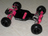
New Design chassis ASSEMBLED PROTOTYPE 18/04/10
-
AYKBOBCAT
- Approved Member
- Posts: 585
- Joined: Wed Nov 22, 2006 2:32 pm
- Location: Bas St-Laurent, Canada
Re: New Design chassis in plan UPDATE 21/02/10
Hey no worries, I would not have thought of it myself. It's my partner that thought of it (it's pretty much his job to do this kind of drawing and all... not for RC though). So it is indeed a good comment and we will consider it. Maybe we can make an even "rounder" shape to avoid this kind of problem. We're trying to make the best possible design while keeping it simple. So all comments are taken constructively. Cheers

Re: New Design chassis in plan UPDATE 21/02/10
jwscab, You seem to know alot about metal. Do you think it needs to be bent this much? To me it still seems like alot. Maybe half that again? 5 deg?
If the sides were bent back down to be flat, or as close as possible, wouldn't it be just as strong as it is now. Doesn't the increased strength come from the "line" that was created by the bend not the wings of the bend?
If the sides were bent back down to be flat, or as close as possible, wouldn't it be just as strong as it is now. Doesn't the increased strength come from the "line" that was created by the bend not the wings of the bend?
-
jwscab

- Approved Member
- Posts: 6580
- Joined: Wed Jan 28, 2009 9:42 am
- Location: Chalfont, PA
- Has thanked: 16 times
- Been thanked: 505 times
Re: New Design chassis in plan UPDATE 21/02/10
the more you bend it, the stiffer the chassis will be, up to 90 degrees. Whether 5 or 10 degrees is enough would really be a subjective test. You would have to bend it and see how stiff it gets. this is a small model and the sheet it pretty wide, so it's almost adequately stiff as it is. 5 or 10 degrees will probably be about the same, at least it would be hard to feel a difference by trying to hand bend it. This is also enough to make it stiff enough for this application.
if you've ever noticed, the reason the original gold tub is bent with such a wide radius is due to the limitations of the alloy, and trying to get it to flow to the contours without cracking, BTW.
as for me knowing alot about metal, my college professors would disagree, but I work with it as a hobby for alot of side work, so I cant' calculate anything for you, but I can tell you what is 'strong', hahhah....school of hard-knocks as they say.
-
Asso_man!

- Approved Member
- Posts: 3960
- Joined: Thu Aug 03, 2006 7:49 am
- Location: EU
- Has thanked: 40 times
- Been thanked: 82 times
Re: New Design chassis in plan UPDATE 21/02/10
Nice project, I would suggest you include the 2 holes at the rear to attach a stock rear motor guard...
_____________________________________________
_____________________________________________
Come and visit the stable
_____________________________________________
Come and visit the stable
-
AYKBOBCAT
- Approved Member
- Posts: 585
- Joined: Wed Nov 22, 2006 2:32 pm
- Location: Bas St-Laurent, Canada
Re: New Design chassis in plan UPDATE 21/02/10
Thanks for the comment Asso_man but that would not work because the rear is not long enough and it is not curved either (like the gold tub).
The best option esthttically would be to use a motor plate like the litesink or something similar I think.
The best option esthttically would be to use a motor plate like the litesink or something similar I think.
-
jwscab
- Approved Member
- Posts: 6580
- Joined: Wed Jan 28, 2009 9:42 am
- Location: Chalfont, PA
- Has thanked: 16 times
- Been thanked: 505 times
Re: New Design chassis in plan UPDATE 21/02/10
Asso_man is referring to the 2 holes that are usually on the graphite chassis (and rc10gt, nitrods),etc. They allow using a small curved motor guard to be attached. the old ones used to be a gold anodized part and an option. the new one is plastic and very stiff. I think it's a great idea, as it is just 2 additional holes.
here is the truck peice:
http://www3.towerhobbies.com/cgi-bin/wti0001p?&I=LX3356&P=7
if you need dimension for the hole locations, I can get them for you tonight, unless someone beats me to it.
I just put the truck peice on a graphite chassis I have, the only problem I found is that i needed to somewhat notch the guard to fit under the motor plate, as it's designed for the gas truck, and is supposed to hold the receiver pack.
-
AYKBOBCAT
- Approved Member
- Posts: 585
- Joined: Wed Nov 22, 2006 2:32 pm
- Location: Bas St-Laurent, Canada
Re: New Design chassis in plan UPDATE 21/02/10
OK that's a good idea but I will indeed need dimentions and location of the holes as I don't have a graphite nor a GT chassis. The other think I need is the lenght of the plate from the suspension arms to the end of the rear. We based ours on the sassis chassis and therefore it may be too short or too long to allow for a match between the added piece and the motor plate.
-
jwscab
- Approved Member
- Posts: 6580
- Joined: Wed Jan 28, 2009 9:42 am
- Location: Chalfont, PA
- Has thanked: 16 times
- Been thanked: 505 times
Re: New Design chassis in plan UPDATE 21/02/10
pardon the crappy paint drawing.
from center of rear most transmission holes to edge of chassis is 0.8"
from center of rear most transmission holes to center of bumper mount holes is 0.6"
from center to center of bumper mount holes is 1 21/32" inches. that's 1.656". If I am not mistaken, most of the dimensions for the rc10 are in decimal inch, not fractional, so this dimension may very well be 1.65" I used a machinists rule, but it's hard to see 6 thousandths by eye between 2 screws with no finer tick marks to make the decision.....
- Attachments
-
- rc10 graphite chassis rear.JPG (9.93 KiB) Viewed 806 times
- rc10 graphite chassis rear.JPG (9.93 KiB) Viewed 806 times
-
blown5.0
- Approved Member
- Posts: 170
- Joined: Thu May 22, 2008 10:49 am
- Location: Michigan
- Has thanked: 1 time
Re: New Design chassis in plan UPDATE 21/02/10
Are the holes for the motor guard offset on the graphite chassis? I know they are on the RPM molded chassis.
-
jwscab
- Approved Member
- Posts: 6580
- Joined: Wed Jan 28, 2009 9:42 am
- Location: Chalfont, PA
- Has thanked: 16 times
- Been thanked: 505 times
Re: New Design chassis in plan UPDATE 21/02/10
the chassis i have is a composite craft or trinity, or something similar, they all looked pretty close, and I would never be able to tell you for sure.
the hole look like they are pretty close to on-center, the back of the chassis was rounded off at one point, making the measurement difficult. I measure maybe .020" difference, which shouldn't be significant.
how far offset is the rpm chassis?
the hole look like they are pretty close to on-center, the back of the chassis was rounded off at one point, making the measurement difficult. I measure maybe .020" difference, which shouldn't be significant.
how far offset is the rpm chassis?
-
blown5.0
- Approved Member
- Posts: 170
- Joined: Thu May 22, 2008 10:49 am
- Location: Michigan
- Has thanked: 1 time
Re: New Design chassis in plan UPDATE 21/02/10
It is approximately .100" to the right or spur gear side
-
AYKBOBCAT
- Approved Member
- Posts: 585
- Joined: Wed Nov 22, 2006 2:32 pm
- Location: Bas St-Laurent, Canada
Re: New Design chassis in plan UPDATE 21/02/10
Hey JWscab I need a precision regarding your drawing. The rear most tranny holes you draw, those are the large 6 gears tranny ones right not the stealth ones? Thanksjwscab wrote:pardon the crappy paint drawing.
from center of rear most transmission holes to edge of chassis is 0.8"
from center of rear most transmission holes to center of bumper mount holes is 0.6"
from center to center of bumper mount holes is 1 21/32" inches. that's 1.656". If I am not mistaken, most of the dimensions for the rc10 are in decimal inch, not fractional, so this dimension may very well be 1.65" I used a machinists rule, but it's hard to see 6 thousandths by eye between 2 screws with no finer tick marks to make the decision.....
Create an account or sign in to join the discussion
You need to be a member in order to post a reply
Create an account
Not a member? register to join our community
Members can start their own topics & subscribe to topics
It’s free and only takes a minute
Sign in
-
- Similar Topics
- Replies
- Views
- Last post
-
- 25 Replies
- 3019 Views
-
Last post by badhoopty
-
- 11 Replies
- 3619 Views
-
Last post by RC10th
-
- 10 Replies
- 1843 Views
-
Last post by unclemikey1978
-
- 29 Replies
- 5037 Views
-
Last post by Welshy40
-
- 17 Replies
- 3465 Views
-
Last post by hugger19
-
- 2 Replies
- 1418 Views
-
Last post by mikedealer
-
- 17 Replies
- 3888 Views
-
Last post by hugger19
-
- 49 Replies
- 5242 Views
-
Last post by Brandon G
Who is online
Users browsing this forum: No registered users and 2 guests