OK I'm starting a new post as my friend that does the design is a new member here and can't access the buy and sell section.
You can see the start of the discussion here http://www.rc10talk.com/viewtopic.php?f=6&t=14157
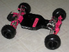
So following the feedback we got from members here we came up with this new chassis design.
One thing to note is that although the front holes looks a bit far on the front plate, they are actually positionned correctly. The fold in the metal is closer to the center of the chassis and explains the difference.
So:
We got rid of the row of holes on the sides
We repositionned the bends to avoid weak points in the chassis
We added holes for the servo posts. QUESTION: are both sets of holes necessary
We changed the angle of the rear part so the chassis has 0° toe-in
What do you guys think? This would most likely be anodized back (but we can choose other colors per batch as well)
Any constructive comments are welcome
New Design chassis ASSEMBLED PROTOTYPE 18/04/10

Re: New Design chassis in plan (testing interests)
Looks good! Only suggestion I have is don't bend the sides up as much. It doesn't take much bend to stiffen it up. I assume you will do the bend on a brake? I would bend it up that much do define the line and then bend it back to almost flat.
-
AYKBOBCAT
- Approved Member
- Posts: 585
- Joined: Wed Nov 22, 2006 2:32 pm
- Location: Bas St-Laurent, Canada
Re: New Design chassis in plan (testing interests)
Thanks
This is a good point. We used the T2 chassis as an example and since my friend lives in a different city and does the drawings, I could only send him a picture
I also though the angle was a bit steep.
We're open to more comments....
Is it still pertinent to have two sets of holes for the servo posts?
-
carloco8

- Approved Member
- Posts: 879
- Joined: Sun Jun 04, 2006 2:02 pm
- Location: SoCal
- Has thanked: 74 times
- Been thanked: 271 times
Re: New Design chassis in plan (testing interests)
Looks great! Just one more hole for the antenna mount........ but even on the T2 chassis it was still in a tight spot.
Old school racing all the way!
-
m_vice

- Approved Member
- Posts: 1312
- Joined: Fri Feb 23, 2007 12:46 pm
- Location: Dallas, TX
- Been thanked: 2 times
Re: New Design chassis in plan (testing interests)
Are you sure about this? the screws should be closer to the bend.AYKBOBCAT wrote:One thing to note is that although the front holes looks a bit far on the front plate, they are actually positionned correctly. The fold in the metal is closer to the center of the chassis and explains the difference.
It is looking good. i would not bend the sides that much. If you look at the flat the sides should be 1/8" from the floor.
i am sure once you make the first test chassis you might make some adjustments to get is a close to perfect as possible.
i am not sure about the servo holes, the T2 chassis had only one set so i would only doe one set of holes not both.

-
blown5.0
- Approved Member
- Posts: 170
- Joined: Thu May 22, 2008 10:49 am
- Location: Michigan
- Has thanked: 1 time
Re: New Design chassis in plan (testing interests)
Just wondering if the sides being angled in so tight, is this going to cause weight distibution problems for mounting the receiver and esc?
The racers here may know.
The racers here may know.
-
scr8p

- Administrator
- Posts: 16810
- Joined: Tue Feb 07, 2006 9:46 pm
- Location: Northampton, PA
- Has thanked: 36 times
- Been thanked: 1318 times
Re: New Design chassis in plan (testing interests)
the front end holes on the sassy chassis were placed in the center of the kick-up. why, i don't know. i always thought it was dumb. but anyway, that's why he's saying the holes are positioned correctly. since he's using a sassy chassis as inspiration.m_vice wrote:Are you sure about this? the screws should be closer to the bend.AYKBOBCAT wrote:One thing to note is that although the front holes looks a bit far on the front plate, they are actually positionned correctly. The fold in the metal is closer to the center of the chassis and explains the difference.
in my opinion, you shouldn't use an aftermarket chassis as a hole template. put the holes in the kick-up closer to the bend, just like a factory nose plate or chassis.
-
AYKBOBCAT
- Approved Member
- Posts: 585
- Joined: Wed Nov 22, 2006 2:32 pm
- Location: Bas St-Laurent, Canada
Re: New Design chassis in plan (testing interests)
Scr8p has a good point.m_vice wrote:Are you sure about this? the screws should be closer to the bend.AYKBOBCAT wrote:One thing to note is that although the front holes looks a bit far on the front plate, they are actually positionned correctly. The fold in the metal is closer to the center of the chassis and explains the difference.
It is looking good. i would not bend the sides that much. If you look at the flat the sides should be 1/8" from the floor.
i am sure once you make the first test chassis you might make some adjustments to get is a close to perfect as possible.
i am not sure about the servo holes, the T2 chassis had only one set so i would only doe one set of holes not both.
We'll check again and reposition the holes , but this is a minor issue I think. I mean we'll obviously make a prototype.
I also think one set of servo holes is enough.
For the bends, We'll wait for more comments. I agree that as it is now it's too much. What is the angle on the T2? Someone as a tool to measure it?
-
AYKBOBCAT
- Approved Member
- Posts: 585
- Joined: Wed Nov 22, 2006 2:32 pm
- Location: Bas St-Laurent, Canada
Re: New Design chassis in plan (testing interests)
What does that looks like? We're also taking suggestions for a follow up option (worlds stup etc.)...badhoopty wrote:i would love an aluminum chassis with a&l swingaxle mounts built-in...
-
longboardnj

- Approved Member
- Posts: 1337
- Joined: Sun Jun 29, 2008 11:52 am
- Location: new jersey
- Been thanked: 2 times
Re: New Design chassis in plan (testing interests)
QUESTION: are both sets of holes necessary for steering servo?? no only need 1 set.... looks very nice..
-
Lowgear

- Administrator
- Posts: 4392
- Joined: Tue Feb 07, 2006 1:00 pm
- Location: New England
- Has thanked: 121 times
- Been thanked: 792 times
Re: New Design chassis in plan (testing interests)
With the sides bent up like that the whole thing reminds me of a *ahem* sanitary napkin 

Now that i've ruined it for everybody I think you're on to something and would be interested in one myself.
Now that i've ruined it for everybody I think you're on to something and would be interested in one myself.
-
AYKBOBCAT
- Approved Member
- Posts: 585
- Joined: Wed Nov 22, 2006 2:32 pm
- Location: Bas St-Laurent, Canada
Re: New Design chassis in plan (testing interests)
That's a good one!Lowgear wrote:With the sides bent up like that the whole thing reminds me of a *ahem* sanitary napkin
Now that i've ruined it for everybody I think you're on to something and would be interested in one myself.
-
AYKBOBCAT
- Approved Member
- Posts: 585
- Joined: Wed Nov 22, 2006 2:32 pm
- Location: Bas St-Laurent, Canada
Re: New Design chassis in plan (testing interests)
OK so far looks like we're making progress again. Thanks for all the comments. It is very much appreciated.
The only real changes I wrote down from this round is
1- move the holes on the front plate closer to the bend
2- Keep only one set of servo holes
3- bend on the chassis should be less steep
Anything else?
A couple of questions:
What angle should we use for the chassis bend? Would using the same as the T2 correct in your opinion?
Which servo holes do you use on your tub chassis?
Should we also put servo holes to mount the servo perpandicular to the chassis?
Should we add another pair of wholes to give the option to move the battery cup forward to allow for 7 cells to be positioned flat? Although most people may now use lipos (I'm not)
Let us know... We'll come back with another drawing...
-
aconsola
- Approved Member
- Posts: 1999
- Joined: Fri Feb 16, 2007 10:09 pm
- Location: Upstate NY
- Been thanked: 12 times
Re: New Design chassis in plan (testing interests)
is there enough room lateral to the servo mount holes to fit a standard size servo there without the bent up portion of the chassis hitting the servo case?
otherwise it looks nice.
otherwise it looks nice.
Create an account or sign in to join the discussion
You need to be a member in order to post a reply
Create an account
Not a member? register to join our community
Members can start their own topics & subscribe to topics
It’s free and only takes a minute
Sign in
-
- Similar Topics
- Replies
- Views
- Last post
-
- 25 Replies
- 3016 Views
-
Last post by badhoopty
-
- 11 Replies
- 3604 Views
-
Last post by RC10th
-
- 10 Replies
- 1843 Views
-
Last post by unclemikey1978
-
- 29 Replies
- 5023 Views
-
Last post by Welshy40
-
- 17 Replies
- 3449 Views
-
Last post by hugger19
-
- 2 Replies
- 1412 Views
-
Last post by mikedealer
-
- 17 Replies
- 3881 Views
-
Last post by hugger19
-
- 49 Replies
- 5237 Views
-
Last post by Brandon G
Who is online
Users browsing this forum: ![]() Amazon [Bot],
Amazon [Bot], ![]() Google [Bot] and 4 guests
Google [Bot] and 4 guests