Joe's Broken Golden Arrow

The place for all things Toy Grade.

Moderators: scr8p, klavy69

JosephS
Approved Member
Posts: 1828
Joined: Thu Mar 23, 2017 5:31 pm
Has thanked: 1213 times
Been thanked: 615 times

Joe's Broken Golden Arrow

Post by JosephS »

I bought a broken golden arrow a while ago because it came with all of the original packing, manuals including the ni-cds and original charger.

I put some batteries in it.
It takes 6x AA batteries for the transmitter
4x AA for the car and 1 Tamiya plug 6 cell nicd

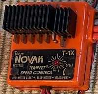
The controller is on channel 6 27.255Mhz

As advertised the car does not work, but in an interesting way, The controller powers on. The car will only power on with the 6 cell nicd attached.

I but batteries in it but used my 5 cell Nicd battery that I use for vintage and testing .
The steering works left and right full proportional.
The throttle only works full forward or full reverse and does so in response to the controller. There is no stop. Adjusting the throttle trim gets to where I can make it flip from forward to reverse, I can't coax it to a stop.

Importantly when I turn off the power to the car, the motor continues running in the last direction selected.

Does anyone know if this is an easy fix? Since the servo and radio appear working.

How do I test if a relay is working properly? Is there anything to check before I de-solder them?


----------------------------------------------------------------------------------
There is a wall of notes below.

I am going to guess that it is the motor driving circuit.

I found this excellent Spanish language website
https://reparar-cochesrc.blogspot.com/p/averias-y-preguntas-frecuentes.html

This page is devoted to older toy grade RC and how each component works. I found this schematic on the page
Untitled 2.png
I was going to guess that the relay was bad, they seems to be working, switching between forward and reverse. So maybe the circuit that drives the relay in having this issue?

The circuit was also shown this way( or this may be from a different board)
Image

the relay is described as
On the electronic plate of the Dictator, the two relays are type H500S03-2-C or MR301-3HS with 3 volt coil and resistance of 25 ohms. The coils are in parallel, so if we measure on the plate it would be about 12.5 ohms. There is a transient suppression diode in parallel with the coils.
Image

I found an image online of a golder arrow receiver board
Untitled 2.png
showing the NEC MR301-3HS relay.
Attachments
DSC02707.jpg

JosephS
Approved Member
Posts: 1828
Joined: Thu Mar 23, 2017 5:31 pm
Has thanked: 1213 times
Been thanked: 615 times

Re: Joe's Broken Golden Arrow

Post by JosephS »

Tutorial on how to test a relay with a multimeter
https://www.etechnophiles.com/test-relay-with-multimeter/


Dadio
Approved Member
Posts: 4062
Joined: Sun Apr 24, 2016 2:21 pm
Location: Guildford UK
Has thanked: 2729 times
Been thanked: 2246 times

Re: Joe's Broken Golden Arrow

Post by Dadio »

I don't know much of these but I fixed one of these type boards for a friend by going over all the solder points on the board with a reflow gun but you could just touch then up with a soldering iron , these old boards were usually pretty robust in the components but suffered from dry solder joints .
If a jobs not worth doing then its certainly not worth doing well.
A problem shared is a problem halved but an advantage shared is no advantage at all.

JosephS
Approved Member
Posts: 1828
Joined: Thu Mar 23, 2017 5:31 pm
Has thanked: 1213 times
Been thanked: 615 times

Re: Joe's Broken Golden Arrow

Post by JosephS »

Thought I would see if I can make this work.

I think the buz11a fets I got for my Novak repairs might work to replace the ones on the board. I also found some cheap relays that look like that may work.


I’m taking some photos in case I break a wire off the board
IMG_6667.jpeg
Wire

Black - antenna
Pink -power switch
Brown- power switch

Orange- servo
Black - servo

White- aa battery box to power switch
Blue- aa battery box to board

Green -servo
White -servo
Blue-servo
Yellow- servo

Thick
Blue-motor
White-motor
Black -battery
Black-shunt wire between relays
Red battery

JosephS
Approved Member
Posts: 1828
Joined: Thu Mar 23, 2017 5:31 pm
Has thanked: 1213 times
Been thanked: 615 times

Re: Joe's Broken Golden Arrow

Post by JosephS »

IMG_6669.jpeg
IMG_6668.jpeg
Someone on the internet had the same trouble as me on

https://forum.digikey.com/t/nec-n8700-to-220-transistor-cross/7978/6


They used this one and reported getting the device to work.

I’ll see how much that overlaps with the devices I have.

First going to test the device again before I tear it down and make sure it’s not working

JosephS
Approved Member
Posts: 1828
Joined: Thu Mar 23, 2017 5:31 pm
Has thanked: 1213 times
Been thanked: 615 times

Re: Joe's Broken Golden Arrow

Post by JosephS »

Looking at the bottom of the circuit board there is an obviously broken trace near the motor white wire on the board

User avatar
TRX-1-3
Approved Member
Posts: 2033
Joined: Sat Mar 29, 2014 12:13 pm
Location: USAG Humphreys, South Korea
Has thanked: 1995 times
Been thanked: 957 times

Re: Joe's Broken Golden Arrow

Post by TRX-1-3 »

JosephS wrote: Wed May 07, 2025 7:09 pm Looking at the bottom of the circuit board there is an obviously broken trace near the motor white wire on the board
Can broken traces be repaired?
Hope you're doin' something fun.

User avatar
Frankentruck
Super Member
Posts: 3704
Joined: Fri Feb 19, 2021 9:59 am
Location: Texas, USA
Has thanked: 2536 times
Been thanked: 2863 times

Re: Joe's Broken Golden Arrow

Post by Frankentruck »

TRX-1-3 wrote: Fri May 09, 2025 8:50 am
JosephS wrote: Wed May 07, 2025 7:09 pm Looking at the bottom of the circuit board there is an obviously broken trace near the motor white wire on the board
Can broken traces be repaired?
A wire could be soldered to each side as a jumper to bridge offer the damaged area.
Frankensteined RC10T3 / Franky Jr RC10GT-e (x2) / A+ stamp / Toy Story RC / Graphite replica / B1.5 BFG 5LTi / Clonewald / Hyper Hornet

"I love the effort, but it sure looks like you took the long way around to a tub again"

1911Colt
Approved Member
Posts: 1258
Joined: Fri May 06, 2022 9:11 am
Has thanked: 1722 times
Been thanked: 820 times

Re: Joe's Broken Golden Arrow

Post by 1911Colt »

I would cut away the bits of trace that have lifted off the board, and run a wire from the solder connections on either side of the break.

JosephS
Approved Member
Posts: 1828
Joined: Thu Mar 23, 2017 5:31 pm
Has thanked: 1213 times
Been thanked: 615 times

Re: Joe's Broken Golden Arrow

Post by JosephS »

1911Colt wrote: Fri May 09, 2025 10:22 am I would cut away the bits of trace that have lifted off the board, and run a wire from the solder connections on either side of the break.
I just found 2 components that were on the trace a a soldered a small wire between them.

That didn’t work. I pulled the board from the car and will replace with some general purpose hobby gear.

I may try and find a am 27?mhz radio to use the original transmitter , but I don’t want to spend much at all on this car.

User avatar
juicedcoupe
Super Member
Posts: 3462
Joined: Sun Aug 16, 2020 4:05 pm
Location: Pascagoula, MS
Has thanked: 266 times
Been thanked: 2041 times

Re: Joe's Broken Golden Arrow

Post by juicedcoupe »

JosephS wrote: Fri May 09, 2025 10:29 am I may try and find a am 27?mhz radio to use the original transmitter , but I don’t want to spend much at all on this car.
Even though they are 27mhz, most toy grade and hobby grade electronics aren't compatible. They usually just cause interference with each other.
Always looking for new and interesting ways to waste money.

JosephS
Approved Member
Posts: 1828
Joined: Thu Mar 23, 2017 5:31 pm
Has thanked: 1213 times
Been thanked: 615 times

Re: Joe's Broken Golden Arrow

Post by JosephS »

juicedcoupe wrote: Fri May 09, 2025 1:22 pm
JosephS wrote: Fri May 09, 2025 10:29 am I may try and find a am 27?mhz radio to use the original transmitter , but I don’t want to spend much at all on this car.
Even though they are 27mhz, most toy grade and hobby grade electronics aren't compatible. They usually just cause interference with each other.
For now I am just going with a flysky setup and some old speed controllers to get this working.

I have heard that the fully proportional tyco radios are compatible with hobby grade gear and the right crystals.

Create an account or sign in to join the discussion

You need to be a member in order to post a reply

Create an account

Not a member? register to join our community
Members can start their own topics & subscribe to topics
It’s free and only takes a minute

Register

Sign in

  • Similar Topics
    Replies
    Views
    Last post

Return to “Nikko / Tyco / Toy Grade Forum”

Who is online

Users browsing this forum: No registered users and 6 guests