Hi
I made a ne front shock tower for a buggy and for whatever reason the car now has crazy toe out when I press on the front suspension. I think it has to do with the steering link position but I'm not sure I get it completly. There must be someting wrong with the geometry. Does someone know a source of info that explains the proper geometry for a buggy's steering assembly?
I did do a search but I could not find what I was looking for.
Thanks for the help...
Need info on general steering geometry
-
Charlie don't surf

- Approved Member
- Posts: 9284
- Joined: Tue Apr 08, 2008 2:44 pm
- Location: USA
- Has thanked: 356 times
- Been thanked: 470 times
Re: Need info on general steering geometry
There is no hard and fast rule per se. In general the more equal the lengths and longer the steering links are camber links are, the less push and pull on the other components causing undesired effects.
Post up a pic in static, and compression and let's see what you have going on!
Post up a pic in static, and compression and let's see what you have going on!
-
AYKBOBCAT
- Approved Member
- Posts: 585
- Joined: Wed Nov 22, 2006 2:32 pm
- Location: Bas St-Laurent, Canada
Re: Need info on general steering geometry
Here are some picts... The servo saver is not properly centered right now but it does not matter. The problem remains there even if it is ok. I believe there is a geometry problem with the steering link. Do all links have to be parallel?
- Attachments
-
- DSC023792.jpeg (38.44 KiB) Viewed 1325 times
- DSC023792.jpeg (38.44 KiB) Viewed 1325 times
-
- DSC023782.jpeg (39.08 KiB) Viewed 1325 times
- DSC023782.jpeg (39.08 KiB) Viewed 1325 times
-
- DSC023752.jpeg (39.21 KiB) Viewed 1325 times
- DSC023752.jpeg (39.21 KiB) Viewed 1325 times
-
Charlie don't surf
- Approved Member
- Posts: 9284
- Joined: Tue Apr 08, 2008 2:44 pm
- Location: USA
- Has thanked: 356 times
- Been thanked: 470 times
Re: Need info on general steering geometry
Try to make the camber links and the steering links match the arms as in being parallel to the suspension arms. That is a huge difference right now, also try the steering.g links on the bottom of the steering knuckle
-
AYKBOBCAT
- Approved Member
- Posts: 585
- Joined: Wed Nov 22, 2006 2:32 pm
- Location: Bas St-Laurent, Canada
Re: Need info on general steering geometry
OK will try that... I'm sure there is a simple solution to this...
-
aconsola
- Approved Member
- Posts: 1999
- Joined: Fri Feb 16, 2007 10:09 pm
- Location: Upstate NY
- Been thanked: 12 times
Re: Need info on general steering geometry
The length and angle of the a-arm, camber link and steering links are all different which is going to make for some funky geometry. The arc swung by the 3 components is going to be different from each other, so the outboard ends are going to move relative to each other when the suspension is cycled(unlike the inner ends of each which are fixed in relationship for any given steering position)
The goal is to get the 3 rods to travel through a similar section of a similar sized arc to get minimal toe/camber changes through the cycle.
play with this to see what different length and position of rods does to the kingpin angle
http://www.racingaspirations.com/?p=286
To fix your problem I think that bottom mounting the tie-rod ends and using longer steering knuckles to get shorter tie-rod lengths will help, similar to the customworks setup here on post 43/44:
http://www.dirtoval.com/forums/showthread.php?t=63823&page=2
-
Jay Dub
- Approved Member
- Posts: 1136
- Joined: Tue Jul 29, 2008 1:04 am
- Location: San Jose, Ca.
- Been thanked: 2 times
Re: Need info on general steering geometry
Those cars always had issues with geometry. Part of the problem is that the steering arms are soo much longer than the suspension itself. If you raise the inner pivot points (the balls on the servo saver) for your steering, eventually you will find a happy medium, and may eliminate it (bump steer) entirely. -Jeff
-
AYKBOBCAT
- Approved Member
- Posts: 585
- Joined: Wed Nov 22, 2006 2:32 pm
- Location: Bas St-Laurent, Canada
Re: Need info on general steering geometry
aconsola wrote:play with this to see what different length and position of rods does to the kingpin angle
http://www.racingaspirations.com/?p=286
OK so from what I understan with this (great online tool by the way!), Rods have to be perfectly parallel and OF THE SAME LENGHT!
I'll try to acheive that...
Thanks
-
Jay Dub
- Approved Member
- Posts: 1136
- Joined: Tue Jul 29, 2008 1:04 am
- Location: San Jose, Ca.
- Been thanked: 2 times
Re: Need info on general steering geometry
Not necessarily, but the closer the better. The AYK cars weren't designed that way  , so there will be some compromise. -Jeff
-
Coelacanth

- Approved Member
- Posts: 7421
- Joined: Thu Jul 29, 2010 6:20 pm
- Location: Alberta, Canada
- Has thanked: 16 times
- Been thanked: 325 times
Re: Need info on general steering geometry
I'm dealing with a similar issue with Barney's heavily customized front end. I'm thinking the culprits contributing to the problem most are my aftermarket alloy C-hubs, which change the angle of the steering knuckles...such that when the suspension is depressed, some combination of the tie-rods & camber links pulls in the knuckles, and toe-out happens.
This is also known as "bump steer" and other sources I researched suggested it's not a bad thing (and may even be good) for offroad, but definitely not desireable for on-road cars.
My CYANide car and my stock Zebra Optima have absolutely zero bump steer.
This is also known as "bump steer" and other sources I researched suggested it's not a bad thing (and may even be good) for offroad, but definitely not desireable for on-road cars.
My CYANide car and my stock Zebra Optima have absolutely zero bump steer.
Completed projects: CYANide Onroad Optima | Zebra Gold Optima | Barney Optima | OptiMutt RWD Mid
Gallery - Coel's Stalls: Marui Galaxy & Shogun Resto-Mods | FrankenBuff AYK Buffalo | 1987 Buick GNX RC12L3
Gallery - Coel's Stalls: Marui Galaxy & Shogun Resto-Mods | FrankenBuff AYK Buffalo | 1987 Buick GNX RC12L3

Re: Need info on general steering geometry
The rods dont have to be parallel to get rid of bump steer. Are you able to drill another set of holes closer to the center line of the shock tower that you can mount your camber links too? If you can get your camber link and toe links close to the same overall length, you should be in decent shape.AYKBOBCAT wrote:aconsola wrote:play with this to see what different length and position of rods does to the kingpin angle
http://www.racingaspirations.com/?p=286
OK so from what I understan with this (great online tool by the way!), Rods have to be perfectly parallel and OF THE SAME LENGHT!
I'll try to acheive that...
Thanks
Edit: looking at the picture of your shock tower, perhaps you could cut another piece of carbon fiber and use the existing camber link holes to mount a "plate" that you'd use for the new camber link mounting locations.
-
AYKBOBCAT
- Approved Member
- Posts: 585
- Joined: Wed Nov 22, 2006 2:32 pm
- Location: Bas St-Laurent, Canada
Re: Need info on general steering geometry
Thanks... The shock tower will go anyway. It interfere with the body. So I'll make a new part...
-
Coelacanth
- Approved Member
- Posts: 7421
- Joined: Thu Jul 29, 2010 6:20 pm
- Location: Alberta, Canada
- Has thanked: 16 times
- Been thanked: 325 times
Re: Need info on general steering geometry
AYKBOBCAT, I just resolved a pretty significant toe-out bump-steer issue with my custom Optima. The tie-rods (if possible) are supposed to be more or less parallel with the front control arms--but that's in a typical A-arm setup. I think the Bobcat/Buffalo (my buddy has the latter) uses swing-arms, but I figured the principle might more or less apply. I happen to have his Buffalo here, I'm supposed to solder on a bunch of EC3 connectors on all our cars, and figured I'd put my theory--that worked so well on Barney--to the test on his Buffalo. You'll be amazed at the difference.AYKBOBCAT wrote:Thanks... The shock tower will go anyway. It interfere with the body. So I'll make a new part...
Basically, you reverse the ball-ends on the steering knuckles so they're underneath instead of on top. Then, you reverse the ball-ends on the servo saver similarly, so they're on top instead of underneath. This changes the angle of the tie-rods quite significantly. You will also need to either use the top hole of the servo horn (as shown with this Buffalo) or mod it somehow so it won't interfere with the tie-rods when steering left/right.
The result--almost no bump-steer. Kinda makes you wonder who engineered these things, eh?
- Attachments
-
-
-
-
-
Completed projects: CYANide Onroad Optima | Zebra Gold Optima | Barney Optima | OptiMutt RWD Mid
Gallery - Coel's Stalls: Marui Galaxy & Shogun Resto-Mods | FrankenBuff AYK Buffalo | 1987 Buick GNX RC12L3
Gallery - Coel's Stalls: Marui Galaxy & Shogun Resto-Mods | FrankenBuff AYK Buffalo | 1987 Buick GNX RC12L3
-
AYKBOBCAT
- Approved Member
- Posts: 585
- Joined: Wed Nov 22, 2006 2:32 pm
- Location: Bas St-Laurent, Canada
Re: Need info on general steering geometry
-
AYKBOBCAT
- Approved Member
- Posts: 585
- Joined: Wed Nov 22, 2006 2:32 pm
- Location: Bas St-Laurent, Canada
Re: Need info on general steering geometry
Ok I tried Coelacanth's idea and I combined it with another set of parts I had... It's the ball post that usually goes in the front but those are much longer. Noe clue who made those... By putting them at the back of the shock instead of the front the turnubuckles are nearly parallel to the suspension arms. So basically perfect. I took the steering knucles off and the shaft now stays perfectly vertical. There is still a little bit of "bumb steer" but that because of the steering turnbuckles... This thing needs a bellcrank I think...
- Attachments
-
-
-
Create an account or sign in to join the discussion
You need to be a member in order to post a reply
Create an account
Not a member? register to join our community
Members can start their own topics & subscribe to topics
It’s free and only takes a minute
Sign in
-
- Similar Topics
- Replies
- Views
- Last post
-
- 5 Replies
- 731 Views
-
Last post by scr8p
-
- 15 Replies
- 1558 Views
-
Last post by TZona
-
- 1 Replies
- 920 Views
-
Last post by RCveteran
-
- 13 Replies
- 2785 Views
-
Last post by RCHJR
-
- 1 Replies
- 1399 Views
-
Last post by RC10th
-
- 3 Replies
- 1490 Views
-
Last post by drbelleville
-
- 2 Replies
- 1075 Views
-
Last post by bozack
-
- 24 Replies
- 1969 Views
-
Last post by vwjuice
Who is online
Users browsing this forum: 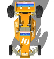 XLR8 and 3 guests